Safety Switches


image

Full-Scale Offering. Solid, Robust Industry Knowledge. Whether you're an end-user or OEM, you face an ongoing challenge: to keep your machines and equipment operating safely and productively, while meeting all global workplace safety standards. When you need comprehensive solutions for machine safeguarding, Honeywell helps you meet the challenge with one of the industry's broadest switch portfolios.

Honeywell offers you choices to ensure that your needs are met in the safety arena. Designed with OEMs in mind, we offer safety switches in every size.


  • Miniature switches – less than 50 mm [2 in] square – for smaller doors and openings.
  • Trapped key and solenoid key switches for large, heavy doors.
  • Cable pull switches for conveyor or perimeter guarding.
  • Non-contacting switches for small door position detection.


Cable Pull Switches:


image

Series CPS/2CPS
Attributes single/dual head cable pull designed to provide emergency stop protection; often used for exposed conveyor and assembly lines
Potential applications conveyor applications, perimeter guard
Housing zinc, epoxy coated
Approvals UL, CSA, CE, SIL 3 capable
Sealing IP67; NEMA 1, 4, 12, 13
Contacts silver, gold
Circuitry (double break contacts, except FF and FFS) • 1NC 1NO
• 2NC 2NO
• 3NC 1NO
• 4NC
Differentiator rugged, sealed, large wiring cavity; indicators; wide temperature tolerance; longest span available (up to 500 feet/152 m on dual head 2CPS)
Measurements (less levers) H x W x D 1CPS: 178,2 mm x 99,1 mm x 65,3 mm [6.8 in x 3.9 in x 2.57 in] 2CPS: 152,4 mm x 165,1 mm x 84,1 mm [6.0 in x 6.5 in x 3.31 in]
Temperature -40 °C to 85 °C [-40 °F to 185 °F]
Electrical rating 10 A (thermal); AC15, A300; DC13, Q300
Features optional hardware packs; heavy-duty terminals: gold contacts; positive opening of NC contacts (up to 4 contacts); LED status lights; positive opening NC contacts


    CLSX Series:


  1. GENERAL INFORMATION (FIGURE 1):
    1. Explosion -proof switches are designed specifically for use in hazardous location applications. Flame paths within the switch housing cool exploding gases below the auto ignition temperature of the atmosphere,
    2. Complies with NEMA standards: 1, 3, 4, 7, 9, 13. UL listed and CSA certified: Div. 1 & 2, Class I, Groups B, C, & D; Div. 1 & 2, Clas s II, Groups E, F, & G,
    3. The CLSX explosion-proof maintained cable-pull limit switch is designed for use in emergency stop applications,
    4. Single-head cable pull limit switch is designed to forcibly disconnect a set of direct acting switch contacts,
    5. Direct acting switch contacts are held closed when actuating cables are under proper tension. When cable is pulled, slackened or broken, a cam posit ively opens the switch contacts,
    6. Switch contacts remain open until switch is reset by manually depressing the reset butt on located on the actuated operating head,
    7. When direct acting switch contacts open, auxiliary contacts also actuate: open contacts close and closed contacts open,
    8. Head may be posit ioned in any of four directions.


  2. image

    MAINTAINED SWITCH:


  3. AUXILIARY CONTACTS:
    1. Additional contacts are electrically isolated from the direct acting switch contacts. They are used for monitoring or signaling, i.e., indicators, pilot lights and alarms.

  4. MAXIMUM ACTUATING CABLE LENGTH:
    1. Depending upon variations in ambient temperature, maximum cable length is 60 m [200 ft].

  5. TENSION INDICATOR:
    1. Convenient tension indicator line on switch plunger indicates maximum preset cable tension.

  6. OTHER AVAILABLE FEATURES:
    1. Conduit opening options.
    2. Hardware kits and cables for various length installations.


  7. INSTALLATION:


    SWITCH MOUNTING, WIRING AND SEALING:


    image
  8. Step 1 - Ensure you have the following:
    1. Switch,
    2. (2) 1/4-20 or (2) 5/16-18 screws,
    3. #14 AWG to #16 AWG stranded or #16 AWG to #18 AWG solid wire.


  9. Step 2 - Mount switch:
    1. Mount using (2) 1/4-20 screws from front of switch, or with (2) 5/16-18 screws from back of switch. Torque to 43 in-lb to 52 in-lb (4.9 N-m to 5.9 N-m).


  10. Step 3 - Wire switch:
    1. With a bar or screwdriver in the cover wrenching lugs, loosen and remove circular cover on front of switch,
    2. Connect stranded or solid wire to switch’s pressure type connector terminals. (Refer to circuit diagram on switch housing. Diagram depicts switch contacts when cable is at proper tension.) Torque terminal screws and ground screw to 7-9 in-lb (0,8-1 N-m),
    3. Reassemble cover and tighten securely.


  11. Step 4 - Seal conduit connection:

    Proper sealing ensures explosion-proof integrity of the conduit system.

    1. Seal in accordance with National Electrical Code, paragraphs 500-2 and 501-4.


  12. ACTUATING CABLE INSTALLATION:


  13. Step 1 - Ensure you have the following (Figure 2):
    1. Plastic coated aircraft cable 3,18 mm [1/8 in] to 4,76 mm [3/16 in] dia. Use a distinctive color, such as red, to differentiate actuating cable from other wires or cables in the area,
    2. Thimbles, U-bolt clamps,
    3. Cable supports (eyebolts).


  14. Step 2 - Attach cable to switch:
    1. Ensure cable is fully seated and tightly fitted in the thimble groove,
    2. Attach using two U-bolt clamps. U-bolt clamps should be installed as close as possible to thimble,
    3. Tighten U-bolts to 0,51 N-m [4.5 in-lb] for 3,18 mm [1/8 in] cable and 0,85 N-m [7.5 in-lb] for 4,76 mm [3/16 in] cable.


  15. Step 3 - Install cable supports:
    1. Install a cable support as close as practical to end of shaft without interfering with switch operation,
    2. If cable tension adjusting turnbuckle is in mid-span of cable, the first cable support should be in line with, and no further than, 30 cm [12 in] from end (eye) of shaft. If adjusting turnbuckle is attached directly to shaft eye, this distance may be increased to 46 cm [18 in],
    3. Support cable at intervals no greater than 2,4 m [8 ft].


  16. SWITCH WITH TURNBUCKLE AND ENDSPRING:


    REQUIRED ENDSPRING AND TURNBUCKLE INSTALLATION:


    image
  17. Step 1 - Ensure you have the following:
    1. Endspring, turnbuckle, jam nuts (supplied with switch),
    2. Thimbles, U-bolt clamps.


  18. Step 2 - Install endspring:

    Reduces effects of ambient temperature fluctuations and provides a measure of protection against excessive force being applied to cable.

    1. Install an endspring within cable span, preferably at end of cable opposite switch (see Actuating Cable Installation, Step 2).


  19. REQUIRED GROUNDING:


    The internal grounding terminal must be used for the equipment grounding connection.

  20. Step 3 - Install turnbuckle:

    Ensures proper cable tension.

    1. Install within cable span in same manner as endspring. Use jam nuts to maintain adjustment.


  21. image

    REQUIRED CABLE TENSION ADJUSTMENT:


  22. Step 1 - Align colored tension indicator line:
    1. Tighten turnbuckle until colored tension indicator line on switch plunger starts to appear from within switch operating head.


  23. Step 2 - Ensure proper adjustment (Figure 4):
    1. Ensure tension indicator line is visible and aligned with end of guide bushing on operating head,
    2. Periodically check and adjust cable tension as necessary.


  24. Cable Tension at Proper Setting:


    With endspring installed, switch/cable will operate satisfactorily over a temperature range of ±12 °C [±25 °F], up to maximum cable length of 60 m [200 ft]. Adjust cable tension when ambient temperature is near mid-point of expected temperature extremes.

    OPTIONAL CORNER INSTALLATION:


    To route actuating cable around a corner, use a free running pulley with a minimum of 10 cm [4 in] dia. Cable should bend no more than 30 degrees as it passes through cable supports spaced no closer than 15 cm [6 in] apart.


    OTHER ADJUSTMENTS:


    To reposition operating head, loosen the four captive screws, place head in desired position. Securely tighten the four screws to 1,36 N-m to 1,80 N-m [12 in-lb to 16 in-lb].


    RECOMMENDED REPLACEMENT:


    Replace entire switch every 100,000 operations.


Key Interlock Switches:


image image

Series GKR/L GKM
Attributes heavy-duty metal body solenoid trapped key interlock switch designed not to release until hazard has been removed; for large doors/cages most compact key-operated safety product available; fully sealed construction
Potential applications large, heavy door, cage and gate machine apps small doors and apertures
Housing zinc, epoxy coated glass-filled polyester
Approvals UL, CSA, CE, SIL 3 capable UL, CSA, CE, SIL 3 capable
Contacts silver, gold silver, gold
Circuitry (double break contacts) • 1NC 1NO slow action BBM
• 2NC 1NO slow action BBM
• 2NC 2NO slow action BBM
• 3NC 1NO slow action BBM
• 2NC slow action
• 4NC slow action
• 2NC 2NO snap action
• 1NC 1NO BBM
• 2NC
Differentiator rugged design withstands vibration, harsh environments; provides long-term durability can be used for doors as small as 160 mm [6.3 in] with small closed radius; available cabled or with integrated M12 connectors for plug and play install
Measurements (less levers) H x W x D 160,0 mm x 110,0 mm x 48,8 mm [6.3 in x 4.33 in x 1.92 in] 69,4 mm x 34,0 mm x 16,0 mm [2.73 in x 1.34 in x 0.63 in]
Temperature -25 °C to 40 °C [-13 °F to 104 °F] -25 °C to 85 °C [-13 °F to 185 °F]
Electrical rating AC15, A300; DC13, Q300 AC15, A300; DC13, Q300
Features solenoid power-to-lock or power-to unlock; key retain force 1000 N max; multiple key and lockout devices; dual LED indicator; available with key entry (4 face orientations); up to 4 contacts; manual override; positive opening NC contacts double insulated, no ground wiring required; wiring entrance options from bottom, side, or both (dual entry GKME for daisy chain capability); variety of keys available for top or front entry options; positive opening NC contact


image image image

Series GKE GKN GK
Attributes 
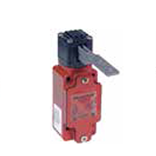
compact housing size, standard IEC 20 mm mounting 
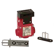
common footprint safety switch for multiple applicability; multiple contacts, multiple key and wiring entry points 
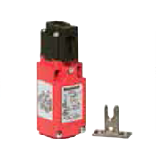
heavy duty metal body keyed interlock switch designed for large doors and cages
Potential applications small doors and apertures small/medium doors and apertures arge, heavy door cage and gate applications
Housing glass-filled polyester glass-filled polyester zinc, epoxy coated
Approvals cULus, CE, S-mark, SIL 3 capable cULus, CE, CCC, S-mark, SIL 3 capable UL, CSA, CE, SIL 3 capable
Sealing IP66/IP67; NEMA 1, 4X (indoor), 12, 13 IP67; NEMA 1, 4X (indoor use only), 12, 13 IP67; NEMA 1, 4, 12, 13
Contacts silver silver silver, gold
Circuitry (double break contacts) • 1NC 1NO snap action
• 1NC 1NO slow action BBM
• 2NC slow action
• 2NC 1NO slow action BBM
• 3NC slow action
• 1NC 1NO snap action
• 2NC 2NO snap action
• 1NC 1NO slow action BBM
• 1NC 1NO slow action MBB
• 2NC 1NO slow action BBM
• 2NC 2NO slow action BBM
• 3NC 1NO slow action BBM
• 2NC slow action
• 4NC slow action
Differentiator small MIN-DIN footprint; simple wiring and mounting; double insulated one switch stocking for multiple contact, key entry, and wiring application combinations; large wiring cavity unique friction feature for key retention; rugged design withstands vibration, harsh environments, and provides long-term durability (tested 15 million cycles)
Measurements (less levers) H x W x D 95,7 mm x 30,5 mm x 32,9 mm [3.77 in x 1.20 in x 1.30 in] 90,0 mm x 64,0 mm x 30,0 mm [3.55 in x 2.52 in x 1.18 in] 121,6 mm x 42 mm x 42,6 mm [1.79 in x 1.652 in x 1.68 in]
Temperature -25 °C to 85 °C [-13 °F to 185 °F] -25 °C to 70 °C [-13 °F to 158 °F] -25 °C to 85 °C [-13 °F to 185 °F]
Electrical rating AC15, A300/A600; DC13, Q300 AC15, A600; DC13, Q300 AC15, A300/A600; DC13, Q300
Features medium duty switch covers most common 1NC/1NO and 2NC applications key entry from top and front multi-use, multi-option; up to 3 contacts for additional monitoring; 4 key head entries; knock-out points for wiring entry; double insulated body; rigid and flexible key options available 
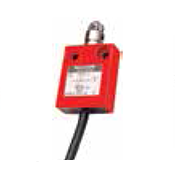
top or side entry lockout device options available; LED indicator; up to four contacts; positive opening NC contacts


Compact And Standard Switches:


image

Series 24CE/924CE
Attributes miniature, compact die-cast zinc housing construction with a wide variety of actuators, IEC945-5-1, EN60947-5-1
Potential applications small doors and apertures
Housing zinc, epoxy coated
Approvals 24CE: CE; 924CE: UL, CE, SIL 3 capable
Sealing IP66
Contacts silver
Circuitry (double break contacts, except FF and FFS) • 1NC slow action,
• 1NC 1NO slow action BBM
• 1NC 1NO slow action MBB
Differentiator smallest safety switch offering from Honeywell; tough and rugged switch, designed to operate in harsh operating environments
Measurements (less levers) H x W x D 49,0 mm x 40,0 mm x 16,0 mm [1.93 in x 1.57 in x 0.63 in]
Temperature 0 °C to 70 °C [32 °F to 158 °F] -40 °C to 70 °C [-40 °F to 158 °F] (optional)
Electrical rating AC15, B300; DC13, R300
Features simple two screw mounting; available pre-wired with choice of cable lengths or connector fitted; side and bottom cable entry; positive opening NC contacts


Non Contact Switches


image

Series FF and FFS
Attributes non-contact safety switches either magnetically operated or by electronically coded magnets providing high degree of tamper-resistant, reliable operation
Potential applications small doors and apertures
Housing ABS resin-filled, stainless steel
Approvals UL, CE
Sealing IP67, NEMA 4
Contacts
Circuitry (double break contacts, except FF and FFS) 1 or 2 safety contacts. Select catalog listings offer an auxiliary contact
Differentiator Large actuation window from almost any angle (ranges ~6 mm to 20 mm); sealed, compact and rugged design
Measurements (less levers) H x W x D 87 mm x 24 mm x 19 mm [3.43 in x 0.95 in x 0.75 in]
Temperature -10 °C to 55 °C [14 °F to 131 °F]
Electrical rating guard status indication; small, easy to mount; either pre-wired or connector fitted; allows for door misalignment with door closed sensing


Safety Switches